Totally Wireless Bird House
by viilaamo.com
Making of
DIY bird house project with Raspberry Pi and Arduino
Here is a detailed explanation how to make a totally wireless surveillance style bird house.
About the design
The main advantage of this device is that it is completely wireless, so you can hang it almost anywhere without worrying the any data or electricity cables. It is powered by the solar panel and the images are sent wirelessly to the network. At the moment the Raspberry Pi is using Wi-Fi dongle to connect a normal household wireless network. You can easily change your connection method by replacing the Wi-Fi dongle with any USB 3G cellular stick modem.
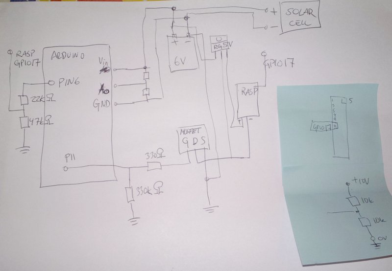
Here is our first draft of the wiring system:
Component shopping list
 Solar panel
SolarXon ES-15P, 15W Standard Power output 15 W Max system Voltage 18.0 V Open circuit Voltage 22.0 V Nominal Voltage 12 V Max Current 0.89 A Height 410 mm Width 350 mm, cost 35€, purchaced from Akkupojat.fi
 Switching voltage regulator
this was clear choice to save energy from the solar panel. 5Volts 1A DE-SW050 cost 16€ (15$ + 1.25$ international shipping)
 Sealed Lead gel battery
6V, 4Ah, Constant voltage charge: Cycle use 7.20V - 7.50V, cost 6,90€, Size 70 × 47 × 101 mm, we purchaced it from motonet.fi
 IRFZ46NLPBF - MOSFET N-CH 55V 53A
2 pcs, 2€/pcs, total cost 4€, can be sourced from your local electronic store
 USB camera Logitech C310
any such old model is suitable, about 15€, should work as plug and play with Raspberry Pi.
 Piece of proto board
This was used to assemble all charge control circuit components and MOSFET's in order to power up and shutdown Raspberry Pi safely, cost 1€
How to design your own charging control unit
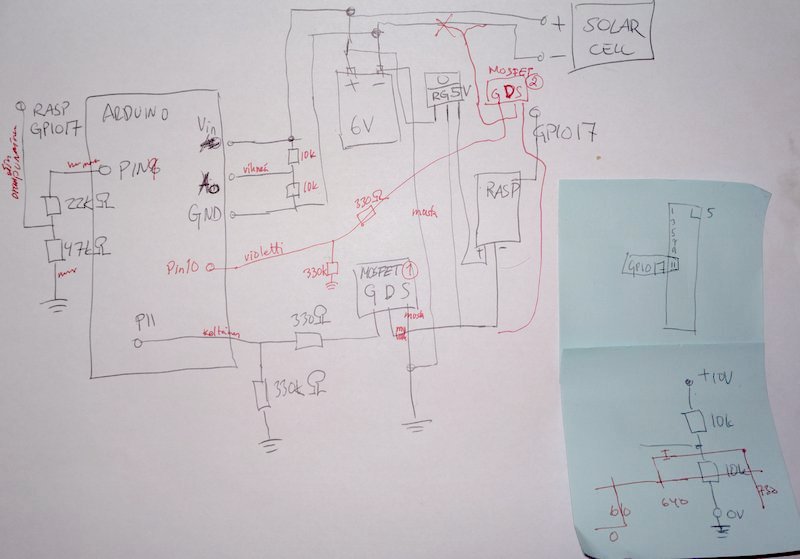
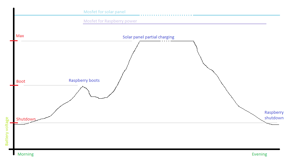
To avoid over charging situation we added one more MOSFET to cut out the solar cell panel when the battery is full. Arduino is measuring the battery voltage via Pin10. When the battery voltage is over the threshold it cuts out the solar cell using MOSFET(2). See the red wiring:)
About the Arduino software
The Arduino SW is controlling one MOSFET to charge the battery from solar panel and the other MOSFET to power the Raspberry Pi. When battery voltage drops too low the Arduino will signal Raspberry Pi using GPIO 17 to give some time to Raspberry Pi to halt the system safely before it cuts the MOSFET(1) off. Be sure to remember that Arduino gives +5 Volts and Raspberry Pi GPIO's are 3.3 Volts, so do not connect Arduino digital pins to Raspberry Pi GPIO pins directly, see left side of the wiring diagram resistors. We used 22k Ohm and 47k Ohm valued resistors.
About the Raspberry Pi software
The Raspberry Pi has a shell script running in infinite loop to check the GPIO 17 if Arduino is trying to shut down the power from the Raspberry Pi. Before the power is cut down Raspberry Pi can finish its job and halt the system safely.
We used WiringPi for easy GPIO access.
Here is the Raspberry Pi side GPIO17 listening loop:
pi@raspberry ~ $ cat safeshutdown
#!/bin/bash

# Make sure everything is up and running
sleep 60

# set GPIO pin 17 for listening
/usr/local/bin/gpio export 17 in

# loop here until shutdown
while true
do

# check the value of pin 17; 1 is up and 0 is down
if (grep 0 /sys/class/gpio/gpio17/value)
then
# value is 0 == pin is down -> time to shut down the system
 echo "0"
# release GPIO pin 17
/usr/local/bin/gpio unexport 17
# do shutdown safely
shutdown -h now
fi

# here is a hack for raspi USB problems; sometimes the
# device changes from video0 to video1 causing camera problems
# VIDIOC_DQBUF: No such device
# in this case we just reboot to recover
if (ls /dev/video0 > /dev/null)
then
# video0 exists, just sleep awhile and move on
sleep 2
else
# video0 has disappeared, do the reboot
reboot
# reboot takes time so sleep awhile
sleep 5
fi

done
Raspberry Pi side code for starting the fswebcam server and two scripts in the boot:
pi@raspberrypi ~ $ cat /etc/rc.local
#!/bin/sh -e
#
# rc.local
#
# This script is executed at the end of each multiuser runlevel.
# Make sure that the script will "exit 0" on success or any other
# value on error.
#
# In order to enable or disable this script just change the execution
# bits.
#
# By default this script does nothing.

# Print the IP address
_IP=$(hostname -I) || true
if [ "$_IP" ]; then
  printf "My IP address is %s\n" "$_IP"
fi

#This starts our own safeshutdown script
nohup /home/pi/safeshutdown > /home/pi/shut.log &

#This starts the fswebcam server to capture vga images
nohup /usr/bin/fswebcam -r 640x480 -S 5 --jpeg 85 --save /var/www/bh.jpg -q -l 50 > \
/home/pi/webcam.log &

#This starts the our own webcast script to wput images to FTP server
nohup /home/pi/webcast > /home/pi/webcast.log &

exit 0
Arduino side code to signal Raspberry Pi and control solar panel charging:
//*************************//
// Copyright:              //
// VIILAAMO.COM            //
// Wireless birdhouse      //
//*************************//

// Pin for voltage measurement
int voltagePin = A0;
// Pin for powering Raspberry
int raspberrypowerPin = 11;
// Pin for connecting solar panel
int solarpanelPin = 10;
// Pin for keepalive pin for Raspberry
int keepalivePin = 9;
// Pin for heartbeat
int ledPin = 13;
float voltageValue = 0;

void setup() {
  // Set output pins and raise the keepalive pin
  pinMode(raspberrypowerPin, OUTPUT);
  pinMode(solarpanelPin, OUTPUT);
  pinMode(keepalivePin, OUTPUT);
  pinMode(ledPin, OUTPUT);
  analogWrite(keepalivePin, 255);
}

// the loop routine runs over and over again forever:
void loop() {
  // Set the solar panel ON for measurement
  analogWrite(solarpanelPin, 255);
  // Wait for awhile to let voltage raise
  delay(50);
  // Measure the value in voltage pin
  // Please note that if the input voltage (VIN) is lower than 7
  // volts then the reference current can be below 5 and hence
  // the measurements are not accurate. Calibrating the values
  // need to happen in real environment, not USB cable connected!
  voltageValue = analogRead(voltagePin);
  // Calibrate the voltage value, in our case 100 is about 1 volts
  // after calibration. This is battery specific value.
  voltageValue = voltageValue * 0.945;

  if (voltageValue > 660) // Above the max charging voltage
  {
    // Disconnect the solar panel for this cycle
    analogWrite(solarpanelPin, 0);
    delay(5000);
  }
  else
  {
    // Keep on charging
    analogWrite(solarpanelPin, 255);
  }
  if (voltageValue > 630)
  {
    // Power on / keep powering Rasperry and set / keep the alive pin up
    analogWrite(raspberrypowerPin, 255);
    analogWrite(keepalivePin, 255);
    digitalWrite(ledPin, HIGH);
  }
  if (voltageValue < 590) // Voltage below minimum level
  {
    // Lower the keepalive pin -> shut down begins
    analogWrite(keepalivePin, 0);
    digitalWrite(ledPin, LOW);
    // Wait for the shut down to finnish
    delay(15000);
    // Power off Raspberry
    analogWrite(raspberrypowerPin, 0);
  }
  // heartbeat and some delay
  delay(1000);
  digitalWrite(ledPin, LOW);
  delay(100);
  digitalWrite(ledPin, HIGH);
  delay(100);
  digitalWrite(ledPin, LOW);
  delay(1000);
}
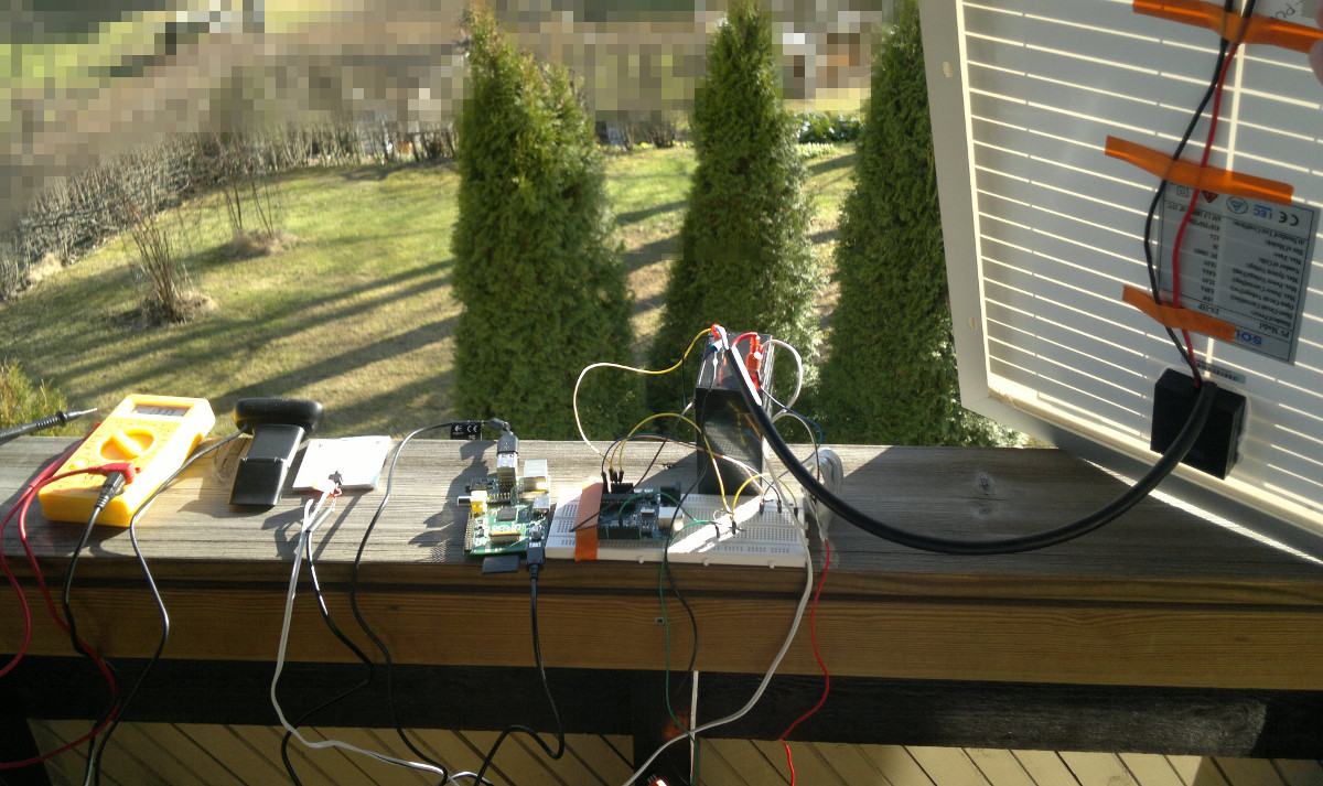
Finally - the complete system
Here is all components bundled together as a Totally 'Wireless' Bird House.
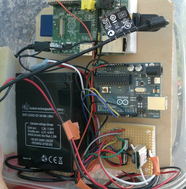
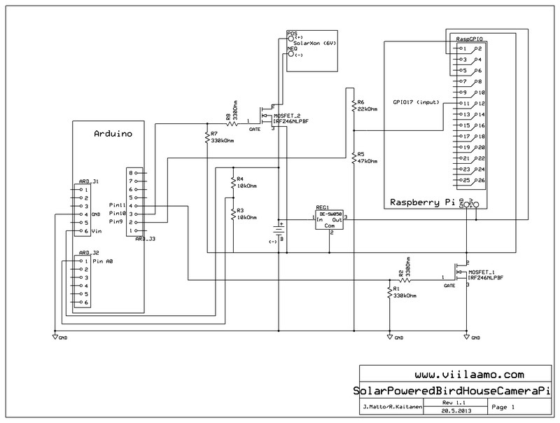
Here is also the final schematics of the solar cell powered Raspberry Pi bird house camera.